

When the ground moves, every structural assembly inside a building is tested — including the raised access floor that hides power, data, and HVAC services beneath the workspace. In high-seismicity regions such as Japan, California, and New Zealand, the design of an office raised floor system is governed by codes that go far beyond ordinary load tables. This article examines the engineering principles, regulatory references, and inspection procedures that structural engineers and facility managers should understand before specifying or signing off on a raised floor in a seismic zone.
Earthquake Risk Background for Elevated Flooring Systems
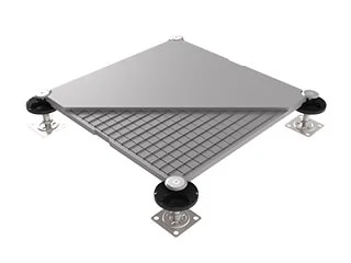
Figure 1. Pedestal and panel assembly evaluated for lateral seismic performance.
A raised access floor is a non-structural component, but during a seismic event it behaves as a coupled mass-spring system above the slab. Pedestal slenderness, panel-to-pedestal friction, and stringer connectivity all influence the floor's response to peak ground acceleration (PGA).
In the 2011 Tōhoku earthquake (M9.0) and the 2014 South Napa earthquake (M6.0), post-event surveys documented panel uplift, pedestal base-plate shearing, and lateral drift exceeding 25 mm on unbraced systems. The lesson from both regions is consistent: gravity-only design is not sufficient where horizontal accelerations exceed 0.4 g.
Design Principles — ASCE 7 Framework (California and U.S. West Coast)
In the United States, raised floors are classified as architectural non-structural components under ASCE 7-22 Chapter 13, which establishes the component amplification factor (a_p), response modification factor (R_p), and importance factor (I_p). For typical office occupancies, designers must verify:
-
Pedestal lateral force F_p ≥ 0.4 × a_p × S_DS × W_p × I_p / R_p
-
Stringer-and-bracket bracing where finished floor height exceeds 300 mm
-
Anchorage of the pedestal base plate using epoxy or mechanical fasteners rated to ICC-ES AC308
-
Verification that panel-to-pedestal connection resists uplift of at least 1.5 × dead load
California's CBC 2022 (Title 24, Part 2) adopts ASCE 7 by reference, with additional OSHPD requirements for hospitals (Risk Category IV) where I_p is set to 1.5 and bracing must be engineered, not prescriptive.
Design Principles — JIS and BSL Framework (Japan)
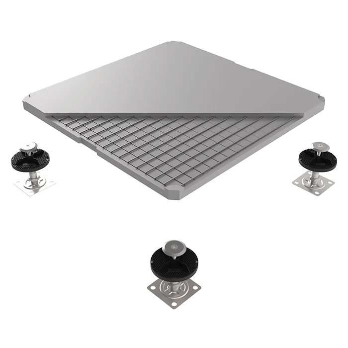
Figure 2. Horizontal load test configuration referenced in JIS A 1450.
Japan's regulatory environment is shaped by the Building Standard Law (BSL) and a series of JIS standards developed in response to the 1995 Kobe and 2011 Tōhoku earthquakes. The most directly applicable documents are:
-
JIS A 1450 — Test methods for raised access floors, including horizontal load tests at 0.5 G and 1.0 G
-
JAFA Performance Classification — Categories A through E, where Category A pedestals must withstand horizontal force equal to panel-plus-live-load weight without permanent deformation
-
BSL Article 20 — Mandates that non-structural components in buildings over 60 m undergo dynamic response analysis
A notable difference between the U.S. and Japanese approaches is the treatment of panel lock-down. Japanese practice typically requires mechanical clips or screws on every panel in data centers and hospitals, whereas U.S. practice often permits gravity-held panels except along egress paths and around heavy equipment.
Pedestal and Stringer Engineering for Seismic Loads
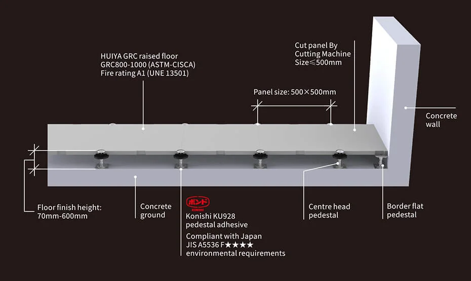
Figure 3. Seismic-rated pedestal with welded head, bolted stringer, and anchored base plate.
The pedestal is the most critical element in seismic performance. Three failure modes dominate post-earthquake forensic reports:
-
Base-plate shear — fasteners pull through or shear off the slab anchor
-
Tube buckling — slender pedestals (FFH > 600 mm) buckle under combined axial and bending
-
Head-plate rotation — the welded head separates from the tube, allowing panels to drop
To resist these failures, seismic-rated pedestals are typically specified with:
-
Steel base plate of 3.0 mm minimum thickness, anchored with two or four fasteners
-
Welded (not glued) head-to-tube joint, tested to 4,500 N lateral load
-
Bolted stringer system forming a continuous diaphragm at the head level
-
Diagonal bracing at the perimeter and at intervals not exceeding 3.0 m in either direction
Video Reference — Shake Table Testing
Video 1. Demonstration of raised access floor behavior on a shake table simulating Zone 4 ground motion. (Replace with actual project URL before publication.)
Inspection and Commissioning Checklist

Figure 4. On-site verification of pedestal anchorage and stringer connections.
Before turnover, a seismic raised floor should pass a documented field inspection. Recommended checklist items include:
-
Pedestal anchor pull-out test on a 2% sample, with results logged to drawings
-
Verification of stringer torque values (typically 8–12 N·m)
-
Confirmation of panel lock-down hardware on every panel in Risk Category III/IV occupancies
-
Photographic record of perimeter closure to walls — gaps must be sealed with compressible filler to prevent panel migration
-
Manufacturer's certificate of compliance with JIS A 1450, ASCE 7, or equivalent
Common Pitfalls in Specification
Even experienced specifiers sometimes mix prescriptive language from one code with performance requirements from another. The most frequent issues observed in design review include:
-
Citing a "1,250 lb concentrated load" rating but omitting any seismic horizontal-load requirement
-
Specifying glued pedestal base plates in zones where ASCE 7 requires mechanical anchorage
-
Allowing finished floor heights above 600 mm without engineered bracing calculations
-
Failing to coordinate floor bracing with under-floor cable trays and CRAC units, which can interfere with diagonal members
Closing Note
Raised floors in seismic regions are not commodities. The difference between a Category A JAFA pedestal and a generic gravity-held assembly may be invisible on a finish schedule, but it is decisive when the building shakes. Engineers, architects, and facility owners working in Japan, California, or any region with design PGA above 0.3 g should treat the access floor as part of the seismic load path — specified, calculated, and inspected with the same rigor applied to ceilings, partitions, and mechanical anchorage.
Disclaimer: This article is a general technical overview and does not replace project-specific engineering analysis. Always consult a licensed structural engineer familiar with local code requirements before finalizing a seismic raised floor design. The image and video URLs are placeholders — please replace them with verified project assets before publishing.